Sunday, November 29, 2015

                                                     ARCH 653- FINAL PROJECT
                                BIM and Visual Programming Applied to L’Oceanagrafic Structure


OVERVIEW  The purpose of this project is to implement Dynamo on the Revit mass models created in the previous project
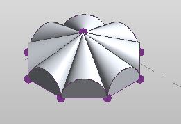
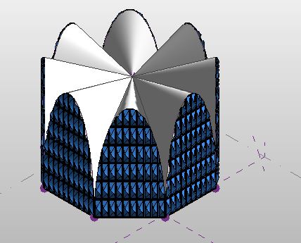
Project-1- Mass Model with Curtain Panels
I have controlled the following tasks using Dynamo Programming

1 Incorporate dynamo programming to control the parameters of the mass model created in Project 1
2 Panel width change based on the Sun Orientation
3 Create a Random Façade for the Structure

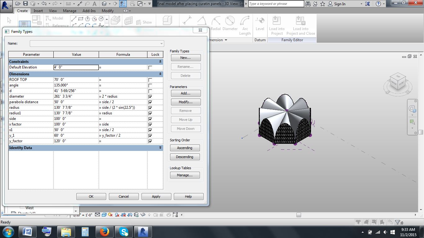
(1) Editing Parameters

Parameters are changed in the model created in Project 1. All the parameters to be changed must be instance parameters. Following are the steps to be followed.

  1.         Open the project model and go to Add Ins tab to launch dynamo
  2.         Using Select Model Element node and select the element to be changed
  3.         Using Get family parameter node, parameters to be changed are connected to dynamo
  4.         Number slider is used to change the values of the respective parameters
  5.         Using number slider and ‘Run Automatically’ option checked, parameter changes can be seen in the Revit view.


I have controlled y_factor, roof top and side of the octagon 
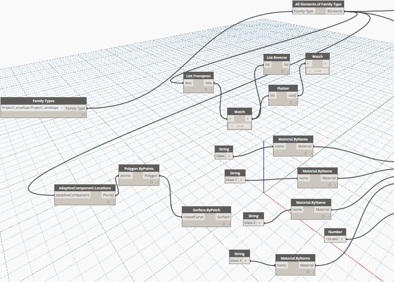
using dynamo program. Dynamo program is as shown
Work Flow for Parameters Change


Side Parameter Change

(2)  Optimum Panel Exposure

The purpose of this task is to show the change in the exposure of panel according to the Sun Orientation. I have used a basic rectangular panel. It has glass surrounded by frame material. I have used the following dynamo code

Rectangular Curtain Panel
  1. Desired curtain panel should be loaded into the mass family
  2. Sun settings should be set at desired location
  3.  Using the Family Types node load the curtain panel family into dynamo
  4.  All Elements of Family Type is used to select all curtain panels of mass model
  5. Work Flow for getting Surface normal for all the elements
  6. Adaptive Component Locations-Polygon By Points-Surface By Patch-Surface Normal at Parameter
  7. Using Sunsettings.SunDirection the position of sun vector is determined
  8. Vector.Dot is found between the sun vector and the surface normal of all the elements
  9. Vector dot values are simplified and linked to the width parameter of curtain panel


Work Flow for Panel Width Change

Work Flow for Panel Width Change


Variation of Exposure along the Day

Optimum Day Lighting- When the angle between the sun vector and the normal vector of the surface is small, intensity of sun is more . So the panels which are facing sun are closed based on the angle. When the angle between the sun vector and the normal vector of the surface is large, intensity of sun is less . So the panels which are facing sun are opened based on the angle.

(3) Randomized Curtain Panel

The Dynamo code developed allows the glass material of the curtain panel to randomly change. I have used the same curtain panel which I have used for my Project 1. Following are the steps for generating randomized curtain panel
Curtain Panel Used for Randomized Material Change


  1. Desired Custom curtain panel should be loaded into the mass model
  2. Launch Dynamo from the Add Ins tool bar
  3. Work flow to be used to generate random custom panel is as follows
Work Flow-1

Work Flow-2

Randomized Curatain Panel


Constraints

  • I had a repeated error while using String node in the Randomized curtain panel. I had to check thoroughly to input the values exactly as they appear in the family. Make sure Material parameters are instance in the family and they must be linked to the type parameters in the model. 
  • While duplicating the material, I had a problem in the appearance of the materials. I rectified it by clicking “Duplicate asset” after selecting the material.
Final Presentation


Monday, November 2, 2015


ARCH 653- MIDTERM PROJECT- L' Oceanografic


OBJECTIVE
The objective of this project is to create a structure using parameters for the building model and facade. The case study I have selected is L’Oceanografic building in Spain. The architect used thin-shell reinforced concrete to create his signature hyberbolic parabola structures. The geometry of the structure was based on the intersection of three lobes that describe the shape of hypar.

Reference- ahistory.wordpress.com
CONCEPTUAL MASS MODEL
The first and the toughest part of this project was to create a conceptual model to form the shape of the building. The shape of the building is octagon. The sides of the octagon were parametrically controlled by the dimensions of the side. The parameter used to create was the internal angle between the two sides of the octagon. Then the next step was to create a point at the center of the octagon. I have controlled the placement of this point parametric with the side dimension of the octagon.

Fig-1- Octagon base of the structure
Next step, is to create a roof structure. The original roof structure was in the shape of the parabola. Due to time constraint I adopted the shape of partial ellipse. The dimensions of the ellipse were parametrically controlled. The length of the major axis was linked to the side of the octagon. The length of the minor axis was given a new parameter that controls the height of roof along the side of the octagon.
Fig-2- Octagon base with partial ellipse along the side

MASS-MODEL
Then solid masses were created. The first mass was created by selecting two radially outward lines and the corresponding partial ellipse for roof structure.  The second mass was created by only selecting the ellipse for the side wall.
Fig-3- Mass Model-Roof Structure

Fig-4-Complete Mass Model

FACADE
The shape of the facade in the original building is rectangular panel. So I have also used the rectangular panel customizing it with sloping surfaces. The height of the surfaces, frame thickness and frame width of my facade can be changed parametrically. I have then loaded this façade parametric pattern to my conceptual mass model.

Fig-4- Parametric Rectangular Curtain Pa

Fig-5- Mass model with nodes


Fig-6- Model with changed curtain panels


PARAMETRIC FAMILIES EXAMPLES
The following figures shown have different parametric values for the mass family.

 Figures 7 and 8 have same dimensions for roof top and roof height along the side. Side of the octagon parameter has been changed.


Figures 9 and 10 have same dimensions for octagon side and roof top. Roof top along the side of the octagon parameter has been changed.


Figures 11 and 12 have same dimensions for octagon side and roof height along the side. Roof top parameter has been changed

CONSTRAINTS
 The first constraint was creating octagonal base for my model. I tried various options by creating a parametric polygon using detail component template. But I was not able to load into mass model.

Fig-13- Parametric parabola

The second constraint was creating hyperbolic parabola roof structure. I have tried various options to create a parametric parabola linking the side of the octagon. I created a parametric parabola by choosing each side of octagon as the reference plane. I selected the vertical plane of the octagon and tried placing points in the shape of the parabola and then joining them using spline. I could join the points on the four sides of the octagon which were on north, south, east and west directions. However I couldn’t change the other four sides as I couldn’t access the elevations of the north-west, north-east, south-west and south-east.

Fig-14- Failed parabola

INTERIOR RENDERINGS

Fig-15-Interior Rendering-1


Fig-16-Interior Rendering-2

EXTERIOR RENDERINGS


Fig-17- Exterior Rendering-1

Fig-18-Exterior Rendering-2

NOTE- Due to time constraint, I couldn't do better renderings than this.